Page 1 of 1
IEC example circuit please
Posted: Tue Jun 08, 2021 12:18 pm
by yellperil
Has anyone implemented/tested the new IEC interface out to real hardware yet?
I'm a bit confused as to how it would work?
I've built one in my custom c64 core using separate Data (in/out) and Clock (in/out) lines like this
https://ist.uwaterloo.ca/~schepers/MJK/serialbus.html
But I don't know how to do it with the lines already combined. Is it simply just whack a logic level converter in and that's it?
I'm assuming it is reliant on the version of the I/O board with pull ups on it.
Re: IEC example circuit please
Posted: Tue Jun 08, 2021 4:27 pm
by jalbarracin
What I understand is that original C64 pins are 5V and MiSTEr works with 3.3V
Hope somebody can clarify this.
Re: IEC example circuit please
Posted: Thu Jun 10, 2021 7:55 am
by yellperil
I've had a go at the circuit but the looking at signals coming out of the FPGA they are at all LOW with no activity on the bus,
They need to be inverted to HIGH so they can be pulled down. ie HIGH being 0 and LOW being 1.
Is there some trickery in the FPGA to be able to Invert them like the 7406?
EDIT : Actually the signals are high, but when I access the external drive they all get pulled low and stay low until the drive is reset.
Re: IEC example circuit please
Posted: Thu Jun 10, 2021 3:29 pm
by aberu
yellperil wrote: ↑Thu Jun 10, 2021 7:55 am
I've had a go at the circuit but the looking at signals coming out of the FPGA they are at all LOW with no activity on the bus,
They need to be inverted to HIGH so they can be pulled down. ie HIGH being 0 and LOW being 1.
Is there some trickery in the FPGA to be able to Invert them like the 7406?
It depends upon if that pin as assigned to the FPGA is compatible with "inout" (verilog/systemverilog) or capable of being an input and/or output. You can also set any of these pins to either in our out. The problem is, if the pins you are using are assigned to the user IO port and they are static in the framework, you may need to adjust the framework side of things in "/sys/" for the template to do this. Your results my vary, proceed carefully.
https://github.com/MiSTer-devel/Templat ... op.v#L1410
I believe this is one of the relevant sections.
I'm not a dev though, so hopefully someone else can weight in and elaborate.
Re: IEC example circuit please
Posted: Sun Jul 04, 2021 10:31 am
by Andre
Re: IEC example circuit please
Posted: Fri Jul 09, 2021 3:05 pm
by yellperil
Embarrassed, pulled it all apart and had another go with colour coded wire and it works a treat, as per the doco.
Re: IEC example circuit please
Posted: Thu Jul 15, 2021 7:43 pm
by jalbarracin
Can you share the color codes or any link where I can learn how to make my own? Thank you!
Re: IEC example circuit please
Posted: Sun Jul 18, 2021 10:33 pm
by jalbarracin
Also, can you explain which board pins do I need to wire? or do I need to connect them to the "USB 3.0" connector?
Re: IEC example circuit please
Posted: Mon Jul 19, 2021 1:10 pm
by yellperil
Sorry for the delay I have been compiling all of my notes.
You can read about it here :
https://8bitshardway.blogspot.com/2021/ ... or-to.html
Re: IEC example circuit please
Posted: Tue Jul 20, 2021 1:35 am
by jalbarracin
GREAT INFO !! BEST BEST!!
Re: IEC example circuit please
Posted: Tue Jul 27, 2021 3:29 pm
by yellperil
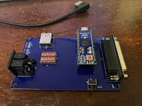
I got my PCB today for my IEC bus / C128 keyboard board. Works very well . . . for me at least.
Re: IEC example circuit please
Posted: Sun Aug 01, 2021 12:50 pm
by venice
Many Thanks.
Got my SD2IEC, just for fun

, running with the notes from your blog.
I use my SNAC Adapter for voltage level conversion (MiSTer 3.3v <=> 5.0v SD2IEC).
I found a matching cable color diagramm here:
https://de.wikipedia.org/wiki/Universal ... dernfarben
and here
https://en.wikipedia.org/wiki/USB_3.0#Pinouts
Re: IEC example circuit please
Posted: Wed Nov 24, 2021 2:11 pm
by jalbarracin
Help needed: Please help me explaining where in the misterfpga is the USB3.0 port where I should connect the IEC expansion cable?
Thank you!
Found this image but can't find the usb3.0 port:
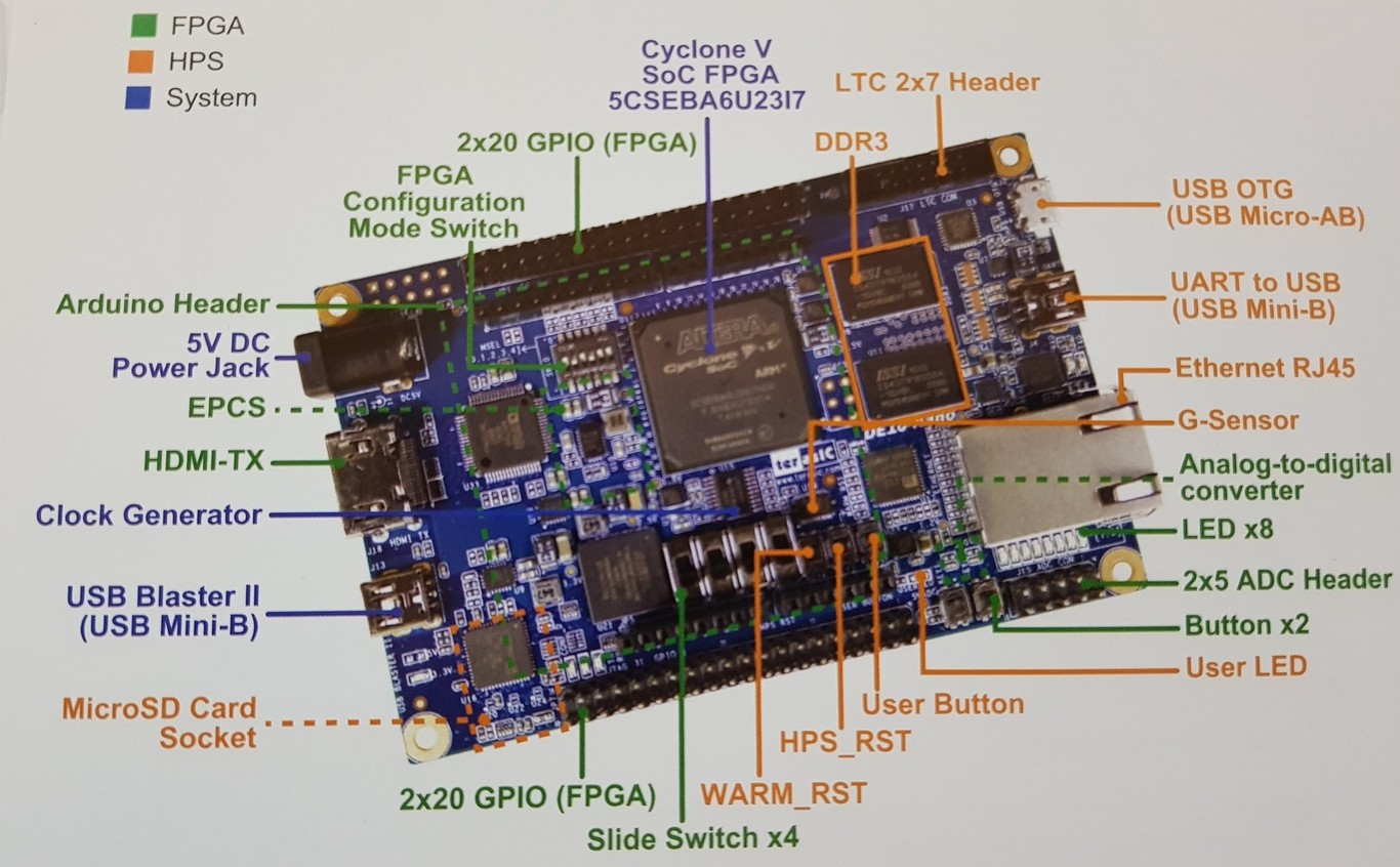
- 1366_2000.jpg (212.5 KiB) Viewed 7936 times
Re: IEC example circuit please
Posted: Wed Nov 24, 2021 2:23 pm
by venice
Re: IEC example circuit please
Posted: Wed Nov 24, 2021 3:07 pm
by jalbarracin
Thank you venice!! I was lost here. best!