Page 1 of 1
IO Board 6.1 Jumper Question
Posted: Tue May 26, 2020 6:19 pm
by foldor
I recently picked up an IO Board 6.1, and I wanted to know what the jumpers on the board do. Most specifically the on in the lower right corner of the picture below near the IO Port. I heard there's some jumper on the board to switch the fan from 3.3V to 5V, but I can't find any documentation on this board anywhere.
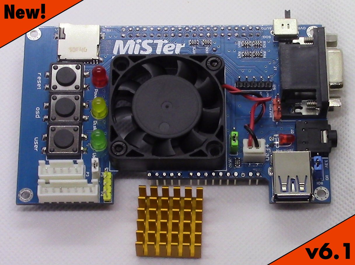
- io61new.jpg (176.16 KiB) Viewed 10006 times
Re: IO Board 6.1 Jumper Question
Posted: Tue May 26, 2020 6:32 pm
by rickdangerous
By your photo is the green jumper, near to the fan connector. In that position is set to 3.3v (silent).
Re: IO Board 6.1 Jumper Question
Posted: Wed May 27, 2020 12:35 pm
by foldor
What about the blue header? Or the white one for that matter? Do you know of any place that documents these things? It even took me a while to find someone talking about the SOG switch being for Sync on Green, which came in handy when I was hooking up via Component.
Re: IO Board 6.1 Jumper Question
Posted: Wed May 27, 2020 4:17 pm
by Nat
The white jumper cap near P3 (5 pin external header connection), when removed assuming the trace on the board below is cut disables all your status LED's (power,disk,user) replace the cap and your have the LED's again, useful when playing in a dark room, or if you wish to have remote status LED's and disable the board mounted LED's.
The blue jumper cap next to the USER IO port is a voltage selector for the USER IO port, under normal use the jumper cap should be connected to the middle pin and the pin marked IO.
Re: IO Board 6.1 Jumper Question
Posted: Thu May 28, 2020 1:35 am
by legacypixels
Blue jumper selects what signal is present on the IO6 pin of the User Port. The 3.3v setting puts 3.3 volts on the pin (same as previous versions of the IO board), The IO setting makes it into an extra data pin (the "pin 7 mod" from older boards). SNAC users with 6 button game pads will use the IO position.
Re: IO Board 6.1 Jumper Question
Posted: Tue Jun 23, 2020 12:59 pm
by foldor
legacypixels wrote: ↑Thu May 28, 2020 1:35 am
Blue jumper selects what signal is present on the IO6 pin of the User Port. The 3.3v setting puts 3.3 volts on the pin (same as previous versions of the IO board), The IO setting makes it into an extra data pin (the "pin 7 mod" from older boards). SNAC users with 6 button game pads will use the IO position.
Ok, so I have anew question. With the IO Board 6.1, what jumpers should I use with a new SNAC board? Does it need to be changed for 6 button pads, and then swapped back for NES pads? Does the SNAC board need the jumper?
Basically, I can't seem to find a lot of good documentation on SNAC, and the jumpers, even on the official Wiki.
Re: IO Board 6.1 Jumper Question
Posted: Wed Jun 24, 2020 1:27 am
by legacypixels
BLUF: I'd need to see which SNAC board design you have to evaluate your situation.
Background: The User port originally provided 6 data lines, GND, +3.3v and +5v. People discovered that you need 7 data lines for some controllers (eg: Sega 6 button). One solution was to run a jumper wire from an IO board data FPGA pin to a JST header on the SNAC. A second method was to cut the 3.3v line on the IO board (6.0 and earlier) and connect a data pin and pull-up resistor instead- the "7 pin mod". On IO v6.1 and Digital IO 1.2, Sorg integrated this modified function into the board design. A jumper chooses between the original behavior (3.3v) or the 7th data pin. (labelled IO6)
There's a couple different SNAC versions floating about, but generally speaking with a v6.1 IO board, you should be able to safely set the IO board IO6 jumper to "I/O" and connect the 7 pin jumper on the SNAC. You shouldn't have to change it back, unless you have some weird design SNAC that doesn't have a 3.3v regulator on it.
But just a follow up, I can't be sure of a particular setup without seeing the SNAC to make sure it isn't some weird design that breaks my assumptions, and could potentially damage your stuff.
Re: IO Board 6.1 Jumper Question
Posted: Mon Jul 20, 2020 2:37 pm
by SSR852
Nat wrote: ↑Wed May 27, 2020 4:17 pm
The white jumper cap near P3 (5 pin external header connection), when removed assuming the trace on the board below is cut disables all your status LED's (power,disk,user) replace the cap and your have the LED's again, useful when playing in a dark room, or if you wish to have remote status LED's and disable the board mounted LED's.
Hey Nat, just received my IO Board 6.1 and other components (RAM). I've installed everything and I can't get the LEDs (TosLink's included) works, I have moved the jumper several time without success, all the rest (the user / reset / osd buttons and the fan are working)
Is there anything I'm missing out?
Thanks!
Re: IO Board 6.1 Jumper Question
Posted: Mon Jul 20, 2020 3:03 pm
by Nat
SSR852 wrote: ↑Mon Jul 20, 2020 2:37 pm
Is there anything I'm missing out?
Thanks!
Sounds like you have the switches on your DE10 Nano setup incorrectly. Set them up like this:
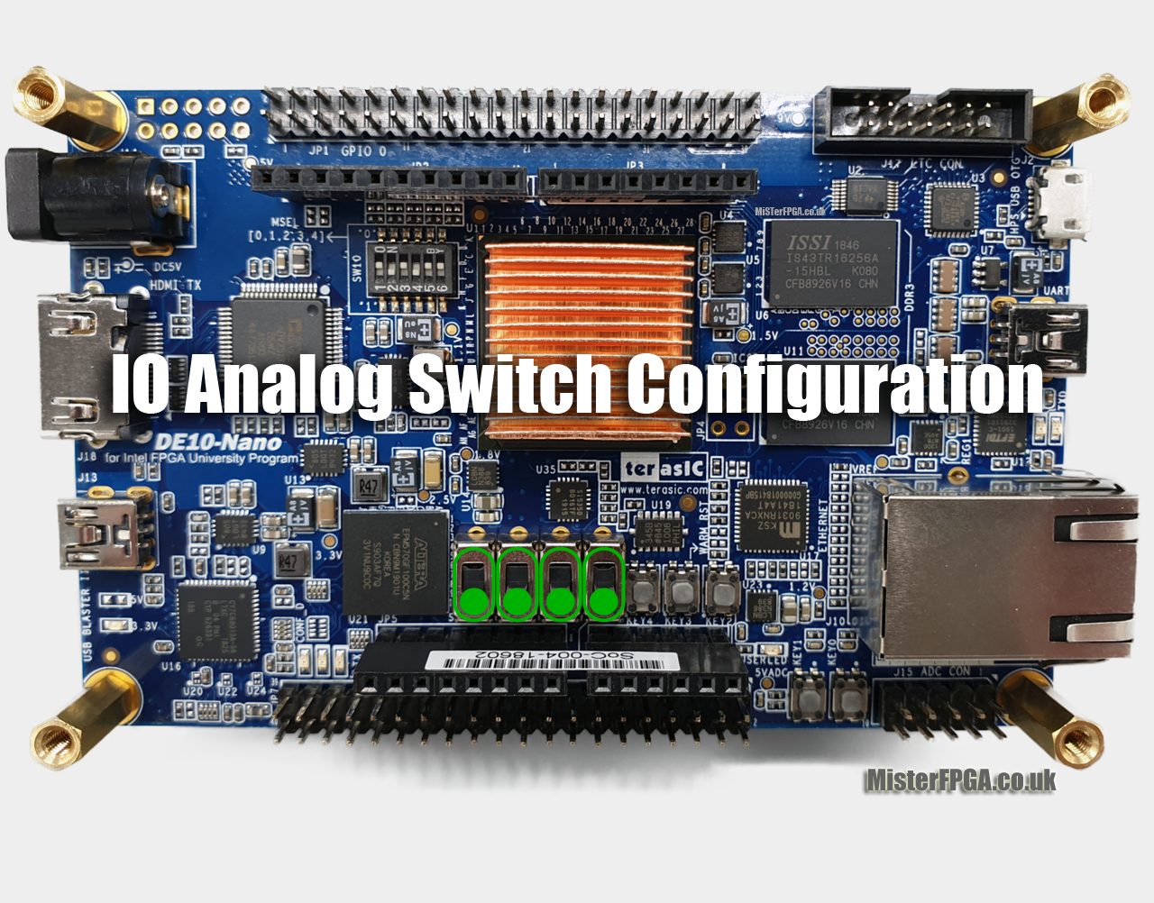
- MiSTer-IO-Board-DE10-Nano-Switch-Configuration-fixed.png (1.44 MiB) Viewed 9873 times
Re: IO Board 6.1 Jumper Question
Posted: Mon Jul 20, 2020 4:46 pm
by SSR852
Nat wrote: ↑Mon Jul 20, 2020 3:03 pm
SSR852 wrote: ↑Mon Jul 20, 2020 2:37 pm
Is there anything I'm missing out?
Thanks!
Sounds like you have the switches on your DE10 Nano setup incorrectly. Set them up like this:
MiSTer-IO-Board-DE10-Nano-Switch-Configuration-fixed.png
Problem solved! Thanks you!
Re: IO Board 6.1 Jumper Question
Posted: Thu Aug 06, 2020 2:03 pm
by chimaera
Does anyone know if the red pins close to analogue out that says VGA PWR 3.3v/5v is the jumper to add voltage to set PAL CRTs to RGB mode?
I cannot find any info about it.
Re: IO Board 6.1 Jumper Question
Posted: Thu Aug 06, 2020 7:08 pm
by chimaera
chimaera wrote: ↑Thu Aug 06, 2020 2:03 pm
Does anyone know if the red pins close to analogue out that says VGA PWR 3.3v/5v is the jumper to add voltage to set PAL CRTs to RGB mode?
I cannot find any info about it.
Never mind found out what it does. Set it to 5V for PAL CRTs.