So, just to be clear. Your MiSTer.ini file only contains that snippet? Did you do the Mr. Fusion installation yourself or was this a pre-installed microSD card? Perhaps try using this instead:
Code: Select all
[MiSTer]
key_menu_as_rgui=0     ; set to 1 to make the MENU key map to RGUI in Minimig (e.g. for Right Amiga)
forced_scandoubler=1   ; set to 1 to run scandoubler on VGA output always (depends on core).
;ypbpr=0               ; set to 1 for YPbPr on VGA output. (obsolete. see vga_mode)
vga_mode=rgb           ; supported modes: rgb, ypbpr, svideo, cvbs. rgb is default.
ntsc_mode=0            ; Only for S-Video and CVBS vga_mode. 0 - normal NTSC, 1 - PAL-60, 2 - PAL-M.
composite_sync=0       ; set to 1 for composite sync on HSync signal of VGA output.
vga_scaler=0           ; set to 1 to connect VGA to scaler output.
hdmi_audio_96k=0       ; set to 1 for 96khz/16bit HDMI audio (48khz/16bit otherwise)
keyrah_mode=0x18d80002 ; VIDPID of keyrah for special code translation (0x23418037 for Arduino Micro)
vscale_mode=0          ; 0 - scale to fit the screen height.
                       ; 1 - use integer scale only.
                       ; 2 - use 0.5 steps of scale.
                       ; 3 - use 0.25 steps of scale.
                       ; 4 - integer resolution scaling, use core aspect ratio
                       ; 5 - integer resolution scaling, maintain display aspect ratio
vscale_border=0        ; set vertical border for TVs cutting the upper/bottom parts of screen (1-399)
;bootscreen=0          ; uncomment to disable boot screen of some cores like Minimig.
;mouse_throttle=10     ; 1-100 mouse speed divider. Useful for very sensitive mice
rbf_hide_datecode=0    ; 1 - hides datecodes from rbf file names. Press F2 for quick temporary toggle
menu_pal=0             ; 1 - PAL mode for menu core
hdmi_limited=0         ; 1 - use limited (16..235) color range over HDMI
                       ; 2 - use limited (16..255) color range over HDMI, for VGA converters.
direct_video=0         ; 1 - enable core video timing over HDMI, use only with VGA converters.
hdr=0                  ; 1 - enable HDR using HLG (recommended for most users)
                       ; 2 - enable HDR using the DCI P3 color space (use color controls to tweak, suggestion: set saturation to 80).
fb_size=0              ; 0 - automatic, 1 - full size, 2 - 1/2 of resolution, 4 - 1/4 of resolution.
fb_terminal=1          ; 1 - enabled (default), 0 - disabled
osd_timeout=30         ; 5-3600 timeout (in seconds) for OSD to disappear in Menu core. 0 - never timeout.
                       ; Background picture will get darker after double timeout
video_off=0            ; output black frame in Menu core after timeout (is seconds). Valid only if osd_timout is non zero.
osd_rotate=0           ; Display OSD menu rotated,  0 - no rotation, 1 - rotate right (+90°), 2 - rotate left (-90°)

vga_sog=0              ; 1 - enable sync on green (needs analog I/O board v6.0 or newer).


; 1 - enables the recent file loaded/mounted.
; WARNING: This option will enable write to SD card on every load/mount which may wear the SD card after many writes to the same place
;          There is also higher chance to corrupt the File System if MiSTer will be reset or powered off while writing.
recents=0

; lastcore - Autoboot the last loaded core (corename autosaved in CONFIG/lastcore.dat) first found on the SD/USB
; lastexactcore - Autoboot the last loaded exact core (corename_yyyymmdd.rbf autosaved in CONFIG/lastcore.dat) first found on the SD/USB
; corename - Autoboot first corename_*.rbf found on the SD/USB
; corename_yyyymmdd.rbf - Autoboot first corename_yyyymmdd.rbf found on the SD/USB
;bootcore=lastcore    ; uncomment to autoboot a core, as the last loaded core.

; 10-30 timeout before autoboot, comment for autoboot without timeout.
bootcore_timeout=10

; Option to load the custom font. Format is plain bitmap 8x8.
; Supported sizes of font:
;   768 bytes - chars 32-127 (only alpha + numeric)
;  1024 bytes - chars 0-127
;  1136 bytes - chars 0-141
;  up to 2048 - only chars 0-141 will be used.
; if first 32 chars are empty (for sizes 1024 bytes and more) then they are skipped.
font=font/myfont.pf

; USER button emulation using a keyboard. Usually it's the reset button.
; 0 - lctrl+lalt+ralt (lctrl+lgui+rgui on keyrah)
; 1 - lctrl+lgui+rgui
; 2 - lctrl+lalt+del
; 3 - same as 0 (lctrl+lalt+ralt on keyrah)
reset_combo=0

; !!!!
; Attention: if video_mode is not set in INI, then MiSTer will try to detect
; native mode of display and use it instead.
; Additionally, if dvi_mode is not set (only if video_mode is not set),
; then MiSTer will try to detect if display is DVI.
; !!!!

; set to 1 for DVI mode. Audio won't be transmitted through HDMI in DVI mode.
;dvi_mode=0

; 0 - 1280x720@60
; 1 - 1024x768@60
; 2 - 720x480@60
; 3 - 720x576@50
; 4 - 1280x1024@60
; 5 - 800x600@60
; 6 - 640x480@60
; 7 - 1280x720@50
; 8 - 1920x1080@60
; 9 - 1920x1080@50
;10 - 1366x768@60
;11 - 1024x600@60
;12 - 1920x1440@60
;13 - 2048x1536@60
;14 - 2560x1440@60
;
; custom mode: hact,hfp,hs,hbp,vact,vfp,vs,vbp,Fpix_in_KHz[,hsyncp,vsyncp]
;  example: video_mode=1280,110,40,220,720,5,5,20,74250,+hsync,-vsync
;
; calculated mode: width,height,refresh[,flags]
;  example: video_mode=1920,1200,60
; flags - cvt=CVT timing, cvtrb=CVT-RB timing (default)
;video_mode=0

; set to 1-10 (seconds) to display video info on startup/change
video_info=0

; Set to 1 for automatic HDMI VSync rate adjust to match original VSync.
; Set to 2 for low latency mode (single buffer).
; This option makes video butter smooth like on original emulated system.
; Adjusting is done by changing pixel clock. Not every display supports variable pixel clock.
; For proper adjusting and to reduce possible out of range pixel clock, use 60Hz HDMI video
; modes as a base even for 50Hz systems.
vsync_adjust=0

; If your monitor doesn't support either very low (NTSC monitors may not support PAL) or
; very high (PAL monitors may not support NTSC) then you can set refresh_min and/or refresh_max
; parameters, so vsync_adjust won't be applied for refreshes outside specified.
; These parameters are valid only when vsync_adjust is non-zero.
refresh_min=0
refresh_max=0

; These parameters have the same format as video_mode.
; You need to supply both PAL and NTSC modes if you want vsync_adjust to switch between
; predefined modes as a base. This will reduce the range of pixel clock.
;video_mode_ntsc=0
;video_mode_pal=7

; Provided below are options for modulating color on the HDMI output.
; Brightness, contrast and saturation can be set to any value between 0 and 100.
; Hue can be set to 0 - 360, observing the HSL color model.
; Each component of video_gain_offset can be set to any value between -2 and 2.
; The order is "gain,offset" repeated three times to cover RGB.
; Example 1, Inverted colors:
; video_gain_offset= -1, 1, -1, 1, -1, 1
; Example 2, Slightly desaturated, warm display:
; video_saturation= 80
; video_gain_offset= 1.5, -0.1, 1.3, -0.15, 0.9, 0.05
video_brightness=50
video_contrast=50
video_saturation=100
video_hue=0
video_gain_offset=1,0,1,0,1,0

; These controls have been provided so you can tweak the HDR metadata values regarding
; peak brightness and average brightness. The defaults are 1000/250 for peak and average
; respectively.
; Some displays will completely ignore the values in the HDR packet, some will make use of them.
; The recommendation is to set hdr_max_nits to your display's peak luminance, while
; setting hdr_avg_nits to at least hdr_max_nits/4.
; Please note that setting a peak brightness far above your display's capability may result
; in clipping in bright parts of the image.
hdr_max_nits=1000
hdr_avg_nits=250

; 1-10 (seconds) to display controller's button map upon first time key press
; 0 - disable
controller_info=6

; JammaSD/J-PAC/I-PAC keys to joysticks translation
; You have to provide correct VID and PID of your input device
; Examples: Legacy J-PAC with Mini-USB or USB capable I-PAC with PS/2 connectors VID=0xD209/PID=0x0301
; USB Capable J-PAC with only PS/2 connectors VID=0x04B4/PID=0x0101
; JammaSD: VID=0x04D8/PID=0xF3AD
;   jamma_vid/pid  (i.e. JammaSD) would be mapped to Players 1 and 2 controllers.
;   jamma2_vid/pid (i.e. J-PAC  ) would be mapped to Players 3 and 4 controllers
;                                 for a possible 4-player JAMMA-VERSUS scenario
;                                 using two JAMMA USB controller interfaces.
jamma_vid=0x04D8
jamma_pid=0xF3AD
jamma2_vid=0x1111
jamma2_pid=0x2222

; Disable merging input devices. Use if only player 1 works.
; Leave no_merge_pid empty to apply this to all devices with the same VID.
;no_merge_vid=0x045E
;no_merge_pid=0x028E

; Same as above but can add multiple devices (one entry per VIDPID). Format is VIDPID in hex number
;no_merge_vidpid=0x12345678
;no_merge_vidpid=0x11112222

; Dead zone radius definitions.
; Joystick movements smaller than a defined radius will be neglected.
; This is good for worn or poorly made joysticks and converters.
; Devices that match the identifier part of the string will be affected.
; You can add multiple devices (one entry per identifier).
; The identifier part is case-insensitive, and the radius can be up to 64 units.
; Identifier and radius are separated by a whitespace (' ') and/or a comma (',').
; Accepted formats are:
;
; - VIDPID as an eight digit hex number ("0x" can be omitted), then the radius (not hex).
;deadzone=0x1E8F1603, 25
;
; - vid:VID as a four digit hex, then the radius.
;deadzone=vid:0x1e8f, 25
;
; - pid:PID as a four digit hex, then the radius.
;deadzone=PID:1603 25
;
; - The following formats are explained a bit further down:
;deadzone=usb-1.2/, 10
;deadzone=7c:10:c9:15:22:33/df:47:3a:12:44:55, 8
;deadzone=1e8f_1603_55c4dd0c, 5

; Permanently assign specific controller to specific player.
; Normally you don't need to use this option, but if you use arcade cabinet with integrated controllers then
; you may want to use it for specific player regardless which controller is used first.
; To assign it, you need to provide unique part of this controller ID.
; In USB debug log you may see list of input devices right after core has been loaded.
; For example:
;
; opened 0( 0): /dev/input/event8 (1915:0040) 0 "7c:10:c9:15:22:33/df:47:3a:12:44:55" "Flydigi APEX2"
; ...
; opened 7( 7): /dev/input/event3 (1997:2535) 0 "usb-ffb40000.usb-1.6/input0" "  mini keyboard"
; opened 9( 9): /dev/input/event0 (046d:4024) 0 "usb-ffb40000.usb-1.2/input2:1/4024-19-a2-39-0a" "Logitech K400"
;
; following part is unique identifier in system ^^^^^^^^^^^^^^^^^^^^^^^^^^^
; So you need to provide part of this string identifying exactly this device. Don't include inputX part as it may change after reboot.
; Wireless devices usually have format MAC/MAC, wired devices use usb-... format.
; UPDATE: you may define up to 8 devices to the same player. Use player_1_controller in several lines to assign multiple devices to player 1.
;
; Example of such unique part of strings:
;
;player_1_controller=usb-1.2/  ;include / at the end so it won't match with something like usb-1.2.3
;player_2_controller=7c:10:c9:15:22:33/df:47:3a:12:44:55
;player_3_controller=1915_0040_55c4dd0c ; VID_PID_HASH - VID, PID and unique HASH
;player_4_controller=1915_0040 ; VID_PID - warning, it will assign all input devices with these VID:PID to same player!


; Speeds in sniper/non-sniper modes of mouse emulation by joystick
; 0 - (default) - faster move in non-sniper mode, slower move in sniper mode.
; 1 - movement speeds are swapped.
sniper_mode=0

; Uncomment following option if you don't want to see a second line for long file names in listing.
;browse_expand=0

; 0 - disable MiSTer logo in Menu core
logo=1

; Custom shared folder for core supporting this feature (currently minimig and ao486 only)
; Can be relative to core's home dir or absolute path.
; Path must exist before core start to use it, or it will fail.
; Make sure USB device is mounted before use shared folder on USB!
shared_folder=

; Custom aspect ratio
;custom_aspect_ratio_1=16:10
;custom_aspect_ratio_2=1:1

; use specific (VID/PID) mouse X movement as a spinner and paddle. Use VID=0xFFFF/PID=0xFFFF to use all mice as spinners.
;spinner_vid=0x1BCF
;spinner_pid=0x0005

; spinner_throttle with base value 100 gives one spinner step per one tick. Higher value makes spinner slower.
; Lower than 100 makes spinner faster. Negative value gives opposite direction.
;spinner_throttle=-50

; 0 - X axis, 1 - Y axis, 2 - wheel.
;spinner_axis=1

; Default filters for video scaler. Paths must be relative to "Filters" folder without leading slash.
;vfilter_default=LCD Effects/LCD_Effect_07.txt
;vfilter_vertical_default=<some_file>
;vfilter_scanlines_default=<some_file>

; Default filters for audio. Paths must be relative to "Filters_audio" folder without leading slash.
;afilter_default=LPF2000_3tap.txt

; Defines internal joypad mapping from virtual SNES mapping in main to core mapping
; Set to 0 for name mapping (jn) (e.g. A button in SNES core = A button on controller regardless of position on pad)
; Set to 1 for positional mapping (jp) (e.g. A button in SNES core = East button on controller regardless of button name)
gamepad_defaults=0

; Write out file name under the cursor in browser for external integration
; External application or script may parse the info and do some additional actions and/or send info to 3rd party server.
; Warning: it may slowdown the system or add lag while browsing the files in OSD depending on external app/script.
log_file_entry=0

; Automatically disconnect (and shutdown) Bluetooth input device if not use specified amount of time.
; Some controllers have no automatic shutdown built in and will keep connection till battery dry out.
; 0 - don't disconnect automatically, otherwise it's amount of minutes.
bt_auto_disconnect=0

; Reset Bluetooth dongle before pair dialog.
; Some dongles may have problem to pair if not explicitly reset.
; Some dongles (mostly CSR) have problem to pair with BLE if not reset in advance.
; Consequence of reset: some input devices get shutdown after reset.
bt_reset_before_pair=0

;default Shadow Mask
;shmask_default=VGA.txt

;default shadow mask mode:
; 0 - none, 1 - 1x, 2 - 2x, 3 - 1x Rotated, 4 - 2x Rotated
;shmask_mode_default=1

; Wait for specific mount before start the core.
; Attention: waiting is performing BEFORE core start, so no message will be displayed on screen!
; It's useful for debugging when core is loaded from USB blaster and games folder is on USB or Network drive.
; This option cannot be used when defmra in CONFSTR is used (i.e. if arcade rbf is loaded directly not through MRA).
; This option is ignored for Menu core.
;waitmount=/media/usb0

; Overrides for video mode
; When the core's video mode matches the parameters in the section header, any options in the section override options from MiSTer and core sections.
; Refresh rate in header is optional and, if present, must match exactly the output from video_info or the logs.  For example, if it says "60.0Hz", the header needs to be "@60.0" to match.
; When the core changes video mode, MiSTer will first look for a matching WIDTHxHEIGHT@VREFRESH section.
; If no match is found, it will fall back to a matching WIDTHxHEIGHT section with no refresh rate.
; If there is still no match, MiSTer/core options will be used without overrides.
; [video=640x400]
; ...
; [video=640x400@70.1]
; ...

; Wheel centering force 0-100. Default is 50.
;wheel_force=50

; Wheel steering angle range. Supported ranges depends on specific wheel model
; If not set then default (depending on driver) range is used
;wheel_range=200

; Enable game mode on HDMI output. It may give you better optimization on some displays, but also
; can give worse result on others. Default is 0 (non-game).
;hdmi_game_mode=1

; Variable Refresh Rate control
; 0 - Do not enable VRR (send no VRR control frames)
; 1 - Auto Detect VRR from display EDID.
; 2 - Force Enable Freesync
; 3 - Force Enable Vesa HDMI Forum VRR
vrr_mode=0
; Minimum framerate in VRR mode.
vrr_min_framerate=0
; Maximum framerate in VRR mode (currently only used in Freesync mode).
vrr_max_framerate=0
; VESA VRR base framerate. Normally set to the current video mode's output framerate
vrr_vesa_framerate=0

; disable autofire if for some reason it's not required and accidentally triggered
disable_autofire=0

; Specify a default video processing preset that will be applied to cores.
; Path is relative to the presets/ directory and can optionally include the .ini extension
;preset_default=General Hardware/Console - 3rdGen

; Enable per controller and per USB port mapping, both gamepads and keyboards
; Even same model of controller connected to different USB ports will have different button sets,
; thus make sure to define buttons for all controllers if you set this option to 1.
; Option also accepts VIDPID value to define per-port mapping only for specific VID:PID device.
; It's useful for DIY controllers using off-the-shelf boards like arduino.
; You may use several controller_unique_mapping instances to assign several VID:PID.
;controller_unique_mapping=0x23418037 ; example for Arduino Micro
controller_unique_mapping=0


; Protect access to the OSD when a core is running
; When attempting to access the OSD players will be prompted for an unlock code.
; U = Up, D = Down, L = Left, R = Right, A = Select, B = Back
; Setting osd_lock to DUUUD would require entering the sequence Down, Up, Up, Up, Down
;osd_lock=DUUUD

; If osd_lock is enabled, allow the OSD to be opened without entering the unlock
; code if less than osd_lock_time seconds have passed since the OSD was closed.
; set to 0 for manual lock from OSD
osd_lock_time=5
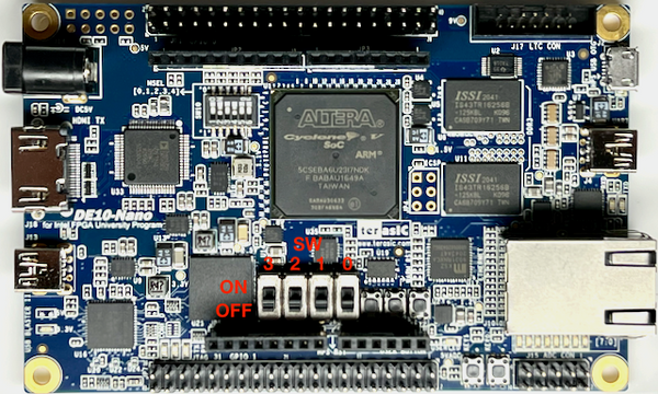
Check the DIP switches are set correctly on the DE10-Nano too (all to off).
If you still aren't getting any lights, something is likely wrong with the IO board.