Page 4 of 6
Re: Real Floppy Drive
Posted: Wed Dec 16, 2020 12:36 pm
by Caldor
Lukage wrote: ↑Tue Dec 15, 2020 4:58 pm
Caldor wrote: ↑Tue Dec 15, 2020 12:41 pm
Wont it also need that USB board? The first point does not seem to go into that. Dont you have a board blueprint for that or something that we can then either make ourselves or order from some PCB maker?
Actually, no, you don't need that board. In this GPIO version, that board serves only as a level converter with open-drain outputs. You just create any type of suitable level conversion for 5V floppy signals, and connect it with analog board. There are holes in analog board on unused GPIO pins, just use some jumper wires. This is that 5 additional GPIO pins. User port has 7 pins in total, on USB3 connector. Just use USB3 A connector with short wires from it, and you are good to go. If you don't have any connector or you don't want to cut any USB3 cable to get a nice pigtail, just solder some jumper wires to analog board on pins used by USB3 user port. Just connect all these wires to some prototyping board (solderless breadboard or some PCB), and do some level conversion on that board.
This is experimental setup, so please don't fry your DE10-Nano boards !
Remember, you can't connect floppy drive directly !
Ahh... I was hoping to not have to make my own USB cables and such. I have some bad experiences short circuiting 2-3 PS/2 keyboards trying to make a micro-USB to PS/2 adapter. Which is why I was hoping there would be a board I could make that would take care of stuff like ensuring its 5V and making it clear which pin goes where. I do not have enough floppy drives, or MiSTers to want to risk doing something this direct, especially when it needs a level conversion. Taking wires between some connectors or soldering a well defined chipset is about the limit of my technical skill when it comes to electronics.
Re: Real Floppy Drive
Posted: Wed Dec 16, 2020 3:56 pm
by Lukage
Yes, this was mainly for those who wanted to experiment before any release. I could post gerbers for CPLD version like in the video, but you would need a way to program Xilinx device, so I wasn't even thinking about it.
I still want to use only a user port, and create board for this user port version, like it was in renders.
It is also possible, that we come to some agreement to use unused pins on Analog board and don't create user port only version. In that case I can draw a simple board with USB3 connector, connector for 5 jumper wires, floppy connector and level conversion using cheap non-programmable parts. It does not affect any peripheral on analog io board, but it is incompatible with MiSTer template.
Re: Real Floppy Drive
Posted: Thu Dec 17, 2020 8:42 am
by Caldor
I can compile FPGA cores, but not sure that helps much. I have looked at code and tried a bit of changing some of it, but its pretty far from what I am used to with C#. I think the most advanced thing I have done with electronics is the USB to PS/2 adapter and recapping a CD32. I do have a project with a ReAmiga 1200, but it just needs some ports to be moved from one board to another as the rest is already done.
I will just wait for a release then. Amazing work though, I hope Sorg is open to implement it. I do think he has plans for using the GPIO pins for a MIDI emulations thing done with a Pi. Both being optional I guess it could just be up to the user what to go with.
Re: Real Floppy Drive
Posted: Fri Dec 18, 2020 10:25 pm
by Lukage
Update: I've corrected some bugs here and there, and added write precompensation logic. Write precompensation follows what is in original Amiga, so there are four levels: 0, 140, 280 and 560ns.
I've thoroughly disassembled and cleaned old SFD-321B drive from Samsung to test with, so I have perfect specimen of a very common drive out in public.
Does anyone attempting to use the published code and is actually connecting a real floppy drive? It would be great if someone can test floppy core on own drive and connection. Also, I would like to know if it would be meaningful to publish any changes and fixes to the code.
Re: Real Floppy Drive
Posted: Fri Dec 18, 2020 11:31 pm
by UgoR934
Hi Lukage, yes, I'll try it during post-Christmas vacations (2-8 January, 2021).. or maybe before, due to the usual "covid last minute lockdowns".
I just have to download the software to look at I/O board schematic and "design" the small prot-board for level-conversion.. doing right now..
I have both Sony and similar floppy drives and some original repaired Chinon drives from Amiga 500. If you want to publish new patches, I'll try them, even not "tomorrow".
Re: Real Floppy Drive
Posted: Sat Dec 19, 2020 12:10 am
by UgoR934
I'm checking the PDF right now of the I/O board trying to figure out the GPIO to use (ex. the 5 unused ones), but I can't find on schematic / PCB. I don't have the I/O board in this house to double check directly on that PCB if something etched over there can help finding out.
Anyway my plan is:
1) Find the correct PINs
2) Make a conversion board with a breadboard: do you have recommendations / schematic for level conversion?
3) Compile the patch and try out
When I figure out everything I'll try to make a small manual with photos for who can want to try.
Re: Real Floppy Drive
Posted: Sat Dec 19, 2020 11:07 am
by Lukage
UgoR934 wrote: ↑Sat Dec 19, 2020 12:10 am
I don't have the I/O board in this house to double check directly on that PCB if something etched over there can help finding out.
If you don't have I/O board, the job is far simpler. Just use DE10-Nano manual, pages 30 and 31. There is Arduino header pinout. As I posted earlier:
Code: Select all
PIN_U14   IO_SCL      STEP
PIN_AG9   IO_SDA      TRACK0
PIN_AF17  USER_IO[6]  DSKRD
PIN_AF15  USER_IO[5]  WPROT
PIN_AG16  USER_IO[4]  DSKCHG
PIN_AH11  USER_IO[3]  DIR
PIN_AH12  USER_IO[2]  SIDE1
PIN_AH9   USER_IO[1]  MOTORB
PIN_AG11  USER_IO[0]  DRVSELB
PIN_AH8   SD_SPI_MISO INDEX
PIN_AG8   SD_SPI_CLK  DKWD
PIN_U13   SD_SPI_MOSI DKWE
And in DE10-Nano user manual:
Code: Select all
Arduino_IO0 PIN_AG13 Arduino IO0 RXD 3.3-V
Arduino_IO1 PIN_AF13 Arduino IO1 TXD 3.3-V
Arduino_IO2 PIN_AG10 Arduino IO2 3.3-V
Arduino_IO3 PIN_AG9 Arduino IO3 3.3-V
Arduino_IO4 PIN_U14 Arduino IO4 3.3-V
Arduino_IO5 PIN_U13 Arduino IO5 3.3-V
Arduino_IO6 PIN_AG8 Arduino IO6 3.3-V
Arduino_IO7 PIN_AH8 Arduino IO7 3.3-V
Arduino_IO8 PIN_AF17 Arduino IO8 3.3-V
Arduino_IO9 PIN_AE15 Arduino IO9 3.3-V
Arduino_IO10 PIN_AF15 Arduino IO10 SS 3.3-V
Arduino_IO11 PIN_AG16 Arduino IO11 MOSI 3.3-V
Arduino_IO12 PIN_AH11 Arduino IO12 MISO 3.3-V
Arduino_IO13 PIN_AH12 Arduino IO13 SCK 3.3-V
Arduino_IO14 PIN_AH9 Arduino IO14 SDA 3.3-V
Arduino_IO15 PIN_AG11 Arduino IO15 SCL 3.3-V
Arduino_Reset_n PIN_AH7 Reset signal, low active. 3.3-V
So you see, you just use jumper wires from Arduino IO header on DE10-Nano.
I regularly use SN74LVC4245A for 3V3 to 5V level conversion. If you want open-drain outputs, just add some 7407 on 5V outputs, and you have also high current drive capability. It is only a example, there are plenty of options out there, depending on what is available in your local electronic parts store.
Re: Real Floppy Drive
Posted: Sat Dec 19, 2020 5:41 pm
by UgoR934
Lukage wrote: ↑Sat Dec 19, 2020 11:07 am
UgoR934 wrote: ↑Sat Dec 19, 2020 12:10 am
I don't have the I/O board in this house to double check directly on that PCB if something etched over there can help finding out.
If you don't have I/O board, the job is far simpler. Just use DE10-Nano manual, pages 30 and 31. There is Arduino header pinout. As I posted earlier:
Sorry, I have written in a hurry: I do have the I/O board, but.. not in the home I was writing (I also have a old Amiga monitor connected to Mister via RGB/SCART).

Anyway, I've a small batch (qt. 8) of CD4050, that a lot of time was used as uni-directional level conversion (by using a Vdd of 3,3V and being confident in his 5V tolerant respect to Vdd input). Do you think I can use these for conversion?
I don't have anything suitable, so.. otherwise, I need to go to a electronic shop or try online.
Finally, if you have a photo "closeup" of wires of your board, would be fantastic!
I originally planned to use an original Amiga 500 to do games during 31/12 end of the year lockdown.. maybe I can have Mister with floppy instead (I already have a 100% working floppy that I sometime use with KryoFlux).
Sorry for asking a lot of things: I'm decent on electronics, but I want just to be 100% sure not to fry anything.. not just for money, but also because it would take weeks to get a replacement, during this special Christmas time.. and, BTW,
Happy Christmas to everyone and.. expecially you, Lukage: I pray a lot of time for a solution like that.. and finally, here it goes! I hope your best for you and your family!
Re: Real Floppy Drive
Posted: Sat Dec 19, 2020 6:02 pm
by Lukage
UgoR934 wrote: ↑Sat Dec 19, 2020 5:41 pm
I've a small batch (qt. 8) of CD4050,
Sure, these can be used, if they are powered with 3V3 supply.
UgoR934 wrote: ↑Sat Dec 19, 2020 5:41 pm
if you have a photo "closeup" of wires of your board
You simply don't need any. Everything is on Arduino header on DE10-Nano. If you have analog I/O board, some pins are populated, and connected to user port. Some are not populated at all, and you can put jumper wire through holes of I/O board directly into DE10-Nano header.
Re: Real Floppy Drive
Posted: Sat Dec 19, 2020 6:34 pm
by UgoR934
Thanks a lot: after taking dinner I will disassemble my "Mister BOX", make some schematic + photo, make a plan.. and, tomorrow, I'll try!
Re: Real Floppy Drive
Posted: Sat Dec 19, 2020 6:41 pm
by C5484
Hi,
Great work, so if i understand correctly, for those who want to replicate your results need a DE10-nano, some wires, lvl converter and a PC floppy drive.
I'm looking for this for a long time now, so THANK YOU for the great work!
I also red some are building case to have the floppy included. I am designing and building a plastic case for the MiSTer, incuding a keyboard and the FDD.
It will take some time, once it's finished i'm sure to share some pictures.
Re: Real Floppy Drive
Posted: Sun Dec 20, 2020 11:09 am
by Lukage
C5484 wrote: ↑Sat Dec 19, 2020 6:41 pm
so if i understand correctly, for those who want to replicate your results need a DE10-nano, some wires, lvl converter and a PC floppy drive
Exactly.
C5484 wrote: ↑Sat Dec 19, 2020 6:41 pm
I am designing and building a plastic case for the MiSTer, incuding a keyboard and the FDD.
Looking forward to it !
Re: Real Floppy Drive
Posted: Sun Dec 20, 2020 2:05 pm
by Lukage
Posting patches & compiled binaries with updated write code.
Re: Real Floppy Drive
Posted: Tue Dec 29, 2020 11:40 pm
by UgoR934
Hi. Thanks a lot Lukage for posting latest patches. To be on the safest side, I tried to double check the code, to check if I understood everything correctly.
I hope that my assumptions are ok.. if you confirm, I will finally try to do it (sorry, but I'm just want to be sure to don't fry anything):
I/O list

- I/O list
- io.gif (95.9 KiB) Viewed 12731 times
DE10-Nano Arduino-compatible header connections
- DE10-Nano Arduino-compatible header connections
- de10-floppy-arduino.gif (294.83 KiB) Viewed 12731 times
Floppy connections
- Floppy connections
- floppy-de10.gif (117.75 KiB) Viewed 12730 times
Thanks in advance for you cooperation.. and.. happy (we hope!) New Year for everybody!
(of course in the middle of DE10 and floppy drive will need to be placed a 5V/3.3V level conversion - I know)
Re: Real Floppy Drive
Posted: Wed Dec 30, 2020 12:08 am
by toastboy
Anyone know of an easy-to-use 12-way level converter (or >12)? Ideally one powered by 5v.
I can find smaller 4-way modules that take 3.3v and convert that to 5v, would love to find a single module that makes things as simple as possible in a USB-powered way.
I have a 5v drive and a bunch of patchleads with pins, just need the converter now.
[edit] also thanks @UgoR934 for restating the pinouts in a simple format, saves us all some effort, assuming @lukage confirms they're correct.
Re: Real Floppy Drive
Posted: Wed Dec 30, 2020 10:10 am
by Lukage
UgoR934, the I/O list is correct. The header connection list is not. I did a quick recheck, and came to this:
Code: Select all
O - USER_IO[0] - AG11 - ARD_IO15 - DRVSELB
O - USER_IO[1] - AH9  - ARD_IO14 - MOTEB
O - USER_IO[2] - AH12 - ARD_IO13 - SIDE1
O - USER_IO[3] - AH11 - ARD_IO12 - DIR
I - USER_IO[4] - AG16 - ARD_IO11 - DSKCHG
I - USER_IO[5] - AF15 - ARD_IO10 - WPROT
I - USER_IO[6] - AF17 - ARD_IO8  - DSKRD
O - GPIO_OUT[0] - IO_SCL   - U14 - ARD_IO4 - STEP
O - GPIO_OUT[1] - SPI_MOSI - U13 - ARD_IO5 - DSKWE
O - GPIO_OUT[2] - SPI_CLK  - AG8 - ARD_IO6 - DSKWD
I - GPIO_IN[0] - IO_SDA    - AG9 - ARD_IO3 - TRACK0
I - GPIO_IN[1] - SPI_MISO  - AH8 - ARD_IO7 - INDEX
This corresponds to your red/green I/O list mapping Arduino I/O to floppy signals. But the actual header connection should look like this:
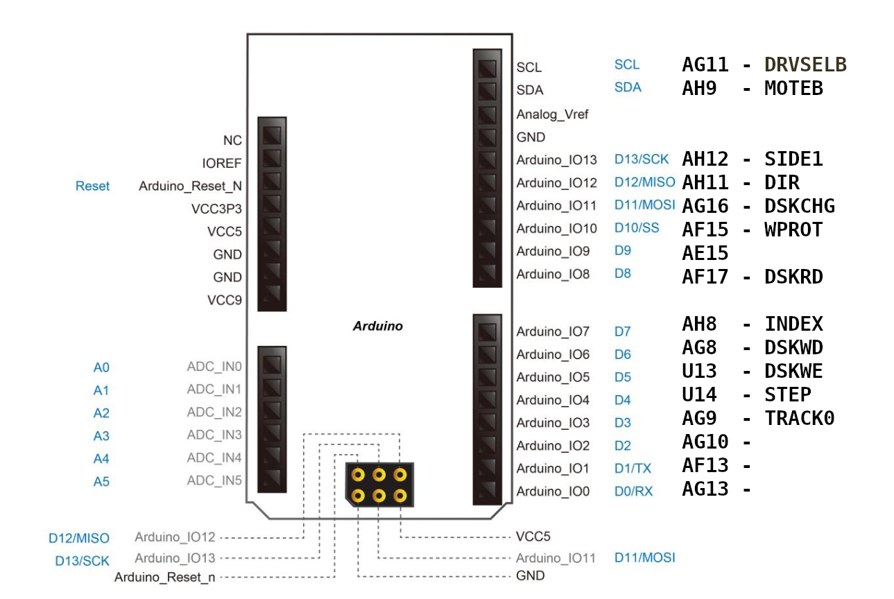
- fpinout.png (410.87 KiB) Viewed 12655 times
Oh, and that argh ao486 note: density select pin is not needed for that. It should work both for DD and HD disks in DOS.
Re: Real Floppy Drive
Posted: Wed Dec 30, 2020 12:34 pm
by UgoR934
Oh, and that argh ao486 note: density select pin is not needed for that. It should work both for DD and HD disks in DOS.
Sorry, not trying to be nitpick.. but just to discover something every day: back in the day, I thought this PIN was needed to format a DD 360K 5"1/4 floppy disk inside a HD 1,2M floppy drive. Is it true or false? I could imagine that 3,5" drives can just auto-configure themselves by checking the second hole, but I can't remember "an hole" for 5 1/4 HD floppies (instead, I could remember that you can force HD format on a SD, of course with disasters coming in seconds).
Also.. THANKS for your updated pinout!
Finally - again

- a request for help.
I checked out CD4050B schematic (the only chip I have to do level conversion here):
- CD4050B
- cd4050b.gif (10.82 KiB) Viewed 12625 times
I looked at I/O schematic (I think you also pointed out) and the output seems open-collector. In input, I don't think I will need anything to get a stable logic. So my proposal is this one (ex. for a single input and a single output):
- I/O level shifting example with CD4050B
- cd4050b-levelconversionexample.gif (58.12 KiB) Viewed 12612 times
Do you think it's ok?
Re: Real Floppy Drive
Posted: Wed Dec 30, 2020 1:02 pm
by Lukage
UgoR934 wrote: ↑Wed Dec 30, 2020 12:34 pm
I thought this PIN was needed to format a DD 360K 5"1/4 floppy disk inside a HD 1,2M floppy drive. Is it true or false?
To be completely honest, I don't know how it was on 5"1/4 drives

. 3,5" PC drives are configured by hole on floppy disk, this selects between 1MB and 2MB total capacity with 300rpm. With DENSEL pin active, DD disks stays at 1MB / 300 rpm, but HD disks are at 1,6MB / 360rpm. IBM PC format is always at 300rpm, thus does not need DENSEL pin.
To schematic, the only thing which is missing is pull-up resistor on TRACK0 floppy drive pin, you would not get logic high without it on your level converter input, those are all open-drain outputs coming from floppy. Just pull all 5 floppy drive outputs (TRACK0, INDEX, WPROT, DSKRD, DSKCHG) to 3V3 with 1k - 2k2 resistor (or practically anything sane you have by your hand
).
Re: Real Floppy Drive
Posted: Thu Jan 14, 2021 10:31 pm
by mlenardon
I have a real Amiga floppy drive mounted in my Checkmate case hoping this project works out. One thought might be to use a Generic usb to floppy controller and jumper the drive accordingly for Amiga use if a PC 3.5. The generic controllers are $10-$20.
Michael
Re: Real Floppy Drive
Posted: Wed Feb 17, 2021 9:01 am
by Caldor
Any news on this?
Re: Real Floppy Drive
Posted: Fri Feb 19, 2021 11:36 am
by toastboy
I've got stuck trying to find a suitable level converter off-the-shelf.
There's this -
https://www.technobotsonline.com/mdfly- ... 3v-5v.html
Which has enough channels to support the 7-outputs and 5-inputs, but is it appropriate for this? What about pullup resistors? Are they needed with this board?
I'll be the first to admit that I have a make-it-up-as-I-go-along approach to electronics, but my hope is that if I can get this working, anyone with a soldering iron can do the same.
Re: Real Floppy Drive
Posted: Fri Feb 26, 2021 11:43 am
by ByteMavericks
Thinking aloud, would it be possible to use this work as the basis for improving the disk activity light to reflect MOTOR_ON as it does in the Amiga - rather than DMA_ON which is what it does now if I understand correctly - and secondly to pass more signals back up to the ARM side with a view to adding in floppy sounds? (Or is that not possible due to the way HDMI is provided by the core?)
Apologies for my ignorance, keen to learn!
Re: Real Floppy Drive
Posted: Fri Feb 26, 2021 4:09 pm
by retrorepair
ByteMavericks wrote: ↑Fri Feb 26, 2021 11:43 am
Thinking aloud, would it be possible to use this work as the basis for improving the disk activity light to reflect MOTOR_ON as it does in the Amiga - rather than DMA_ON which is what it does now if I understand correctly - and secondly to pass more signals back up to the ARM side with a view to adding in floppy sounds? (Or is that not possible due to the way HDMI is provided by the core?)
Apologies for my ignorance, keen to learn!
This would be a simple change but Sorg likes DMA as it's more lively.
I think original behaviour would be preferred personally as DMA doesn't always seem to reflect the disk activity correctly.
This is probably discussion for another topic though.
Re: Real Floppy Drive
Posted: Fri Feb 26, 2021 5:39 pm
by LamerDeluxe
I agree that you'd want the drive light to act like the one of a real Amiga.
Re: Real Floppy Drive
Posted: Fri Mar 05, 2021 11:24 am
by arglmauf
Cheers. I've got a Amiga 500 Case with keyboard on my workbench that just begs to be filled with the MiSTer. Adding a proper floppy to it would be the icing on the cake:D
Any plans the floppy patch will eventually find its way into the core? Or will this stay an enthusiasts project?
Re: Real Floppy Drive
Posted: Wed Apr 21, 2021 1:18 pm
by retrorepair
Lukage wrote: ↑Sun Dec 20, 2020 2:05 pm
Posting patches & compiled binaries with updated write code.
Could you possibly look to get some of the floppy controller improvements merged?
There's no reason they shouldn't be if they achieve more accurate behaviour.
Re: Real Floppy Drive
Posted: Thu May 06, 2021 10:58 am
by retrorepair
UgoR934 wrote: ↑Wed Dec 30, 2020 12:34 pm
Oh, and that argh ao486 note: density select pin is not needed for that. It should work both for DD and HD disks in DOS.
Sorry, not trying to be nitpick.. but just to discover something every day: back in the day, I thought this PIN was needed to format a DD 360K 5"1/4 floppy disk inside a HD 1,2M floppy drive. Is it true or false? I could imagine that 3,5" drives can just auto-configure themselves by checking the second hole, but I can't remember "an hole" for 5 1/4 HD floppies (instead, I could remember that you can force HD format on a SD, of course with disasters coming in seconds).
Also.. THANKS for your updated pinout!
Finally - again
- a request for help.
I checked out CD4050B schematic (the only chip I have to do level conversion here):
cd4050b.gif
I looked at I/O schematic (I think you also pointed out) and the output seems open-collector. In input, I don't think I will need anything to get a stable logic. So my proposal is this one (ex. for a single input and a single output):
cd4050b-levelconversionexample.gif
Do you think it's ok?
Did you get anywhere with this?
Re: Real Floppy Drive
Posted: Sat May 08, 2021 4:55 pm
by Lukage
retrorepair wrote: ↑Wed Apr 21, 2021 1:18 pm
Lukage wrote: ↑Sun Dec 20, 2020 2:05 pm
Posting patches & compiled binaries with updated write code.
Could you possibly look to get some of the floppy controller improvements merged?
There's no reason they shouldn't be if they achieve more accurate behaviour.
To be completely honest, I just can't figure out how to integrate it properly and not compromise any other MiSTer functionality.
For some past months I was busy with other projects, but was still investigating other possibilities of floppy connection. Because it is not possible for unmodified user port to shift signals with enough speed, it is not possible to create cheap simple interface just for user port how it was proposed before.
Right now, I do tend more to STM32 version of floppy controller, like using Greaseweazle, and use USART on STM32 for floppy data, which is completely possible for user port to handle. Or just plug the Greaseweazle unmodified via USB, and lose some functionality, like drive clicks, but gain some more functionality, like usage of raw disk files in MiSTer emulators.
Has anyone used my floppy code and tested it sucessfully ?
Re: Real Floppy Drive
Posted: Thu Jun 03, 2021 5:25 pm
by matbird
Hello! I was wondering if you'd seen this... Looks very interesting, does it have any potential utility for MiSTer?
https://youtu.be/aJ0g7lQQVus
Re: Real Floppy Drive
Posted: Thu Jun 03, 2021 6:57 pm
by limi
Definitely looks like the missing hardware piece for MiSTer’s hardware compatibility for Amigas. Since there’s an integration into WinUAE, it would be great to see if this could be made to work with the Minimig core.
Developer’s web site:
https://amiga.robsmithdev.co.uk
GitHub repository:
https://github.com/RobSmithDev/ArduinoFloppyDiskReader