Page 1 of 1
Hooking up LEDs to LED header on I/O board
Posted: Sat Jan 16, 2021 1:05 am
by GaiusIuliusCaesar
I have jumped right into this whole stuff, and was wondering how you correctly hook LEDs for cases(I am currently designing a custom keyboard one for my self in Fusion360).
This is what I currently have for the led part:
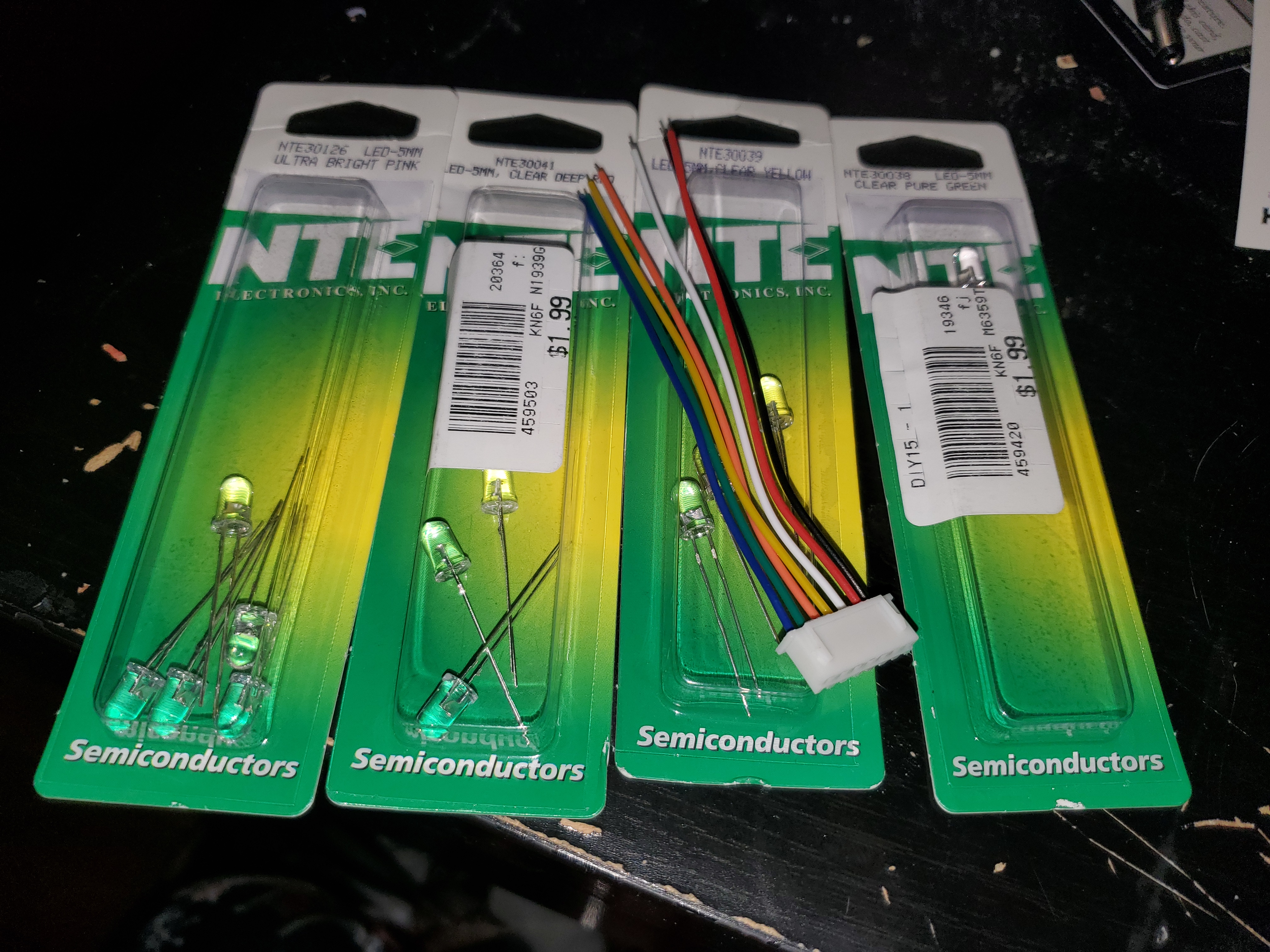
- 20210115_195520.jpg (4.03 MiB) Viewed 2282 times
I don't have any real knowledge of physical electronics so I don't know what I need to connect to what pins and if there are passives needed to make it work or if it is as simple as connect pin to led to ground pin.
Re: Hooking up LEDs to LED header on I/O board
Posted: Sat Jan 16, 2021 1:45 pm
by Xbytez
Re: Hooking up LEDs to LED header on I/O board
Posted: Sat Jan 16, 2021 1:56 pm
by LamerDeluxe
I've replaced the 3mm LEDs on my analog IO board with 5mm ones (after getting an acrylic case), but the green one is much more dim. Turns out all three colors use the same resistors (in a tiny resistor array chip on the 6.1XL version), while green LEDs usually consume about 3 volts and red and yellow 2 volts.
Then I looked at the parts list and a 2.1 volt version of the green LED is suggested. However, I much prefer the pure green (emerald) 525nm LEDs over the common lime-green 565+ nm LEDs. These turn out to be difficult to find at 2.1 volts combined with a green tinted housing, at 5mm diameter. The 3mm one I removed was like that.
So, when looking for replacement LEDs, keep in mind that all three should have about the same brightness (+/- 250mcd suggested in the parts list) at around the same voltage and amperage (20mA).